조회 수: 231, 2015-12-16 22:52:59(2015-12-09)
--------------------------------------------------------------------------------
300B OPT 는 장사꾼들이 3.5Kohm 을 꼭 사용해야 하는 것 같이 선전해왔습니다.
일반 DIYer 도 꼭지켜야 제대로Amp가 동작하는것으로 알고 있습니다.
이 OPT 는 13GB5 Para 용 으로도 사용합니다.
OPT 에서 Load Impedance 의 의미를 정확히 이해하고 있는사람이 드뭅니다.
제가 여러번 이 문제를 설명해서 반복은 하지 않겠습니다 .
OPT에 Spec로 쓰여진 Impedance 는 Trans의 고유정수는 아니고 제작자가 추전하는 Plate Load 값 입니다.
IST Spec은 좀 더 정확 합니다. 대개가 권선비하고 특정 주파수에서의 Inductance값이 나와있습니다.
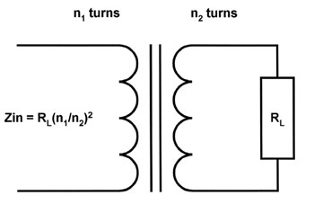
초보자도 꼭알고 있어야 할 1-2차간의 관계식은 권선비의 자승이 Impedance 의 비가 된다는 것입니다.
아시는분은 알기 쉽게 설명 올려 주십시요
예로 1차 1.6K 와 NFB 64옴 2차에 16ohm, 9ohm, 4ohm 의 트랜스를 감는다면 권선비를 40:8: 4:3:2 로
1차측으로 2000:400 턴 2차측에 200:150:100 턴을 감거나, 1차에 1200: 240 2차에 120:90:60 턴을 감든지 선정된 코아의 권선용량에 따라 턴 수를 결정하면 된다는 말씀으로 이해했습니다.
1.7K : 8ohm 이면 14.58 : 1 로 감아야겠네요.
A:
다른분도 이해 하셨다고 봅니다.
1.6K 와 NFB 64옴 2차에 16ohm 9ohm 4ohm -- 1.6-64-16-9-4 ----의미있는 숫자조합 입니다. 특히 16-9-4..
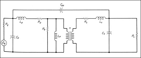
Capacitance (특히 Cps)를 취급한 Transformer Equivalent Circuit 는별로 볼수가 없습니다
저 자신의 참고 자료로 -- For myself --여기에 올렸습니다.
http://www.chooseindia.com/engineering/Understanding-Transformers.htm
 | |||||
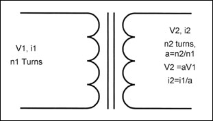
| Figure 2: The ratio of the number of turns in the windings determines the voltage and current ratios present in the windings. They go in opposite directions-if voltage is stepped up, current is stepped down, and vice-versa. | |||||
An ideal transformer will isolate the input circuit from the output circuit, transform the input voltage by the ratio of the number of turns in the windings, and be frequency independent. If the secondary has more turns than the primary, the voltage will be "stepped up"; if the secondary has fewer turns than the primary, the voltage will be "stepped down." The current will change in an inverse fashion. That is, if voltage is stepped up across a transformer, the current will be decreased by the same proportion. This is as it must be to conserve energy. The power that comes out of a transformer must equal the power that is put into it, less any losses due to such factors as magnetic imperfections and resistive heating of the transformer windings. | |||||
Practical Limitations The idealized transformer described above has only the transformation property-it doesn't have any losses, or power limitations. Its frequency response seems to be infinite. Real components have limited efficiency and bandwidth, and can act in a non-linear fashion. A circuit model incorporating these imperfections is shown in Figure 3. The imperfections are shown as equivalent components added to an ideal transformer. | |||||
 | |||||
| Figure 3: Physical effects cause transformers to deviate from the simple idealized model. Shown is a small signal model which includes the effects of shunt and inter-winding capacitance, stray inductance, magnetic loss, and winding resistance. Note that under low frequency or large-signal conditions, the shunt primary inductance can become nonlinear if the transformer is driven into saturation. | |||||
These imperfections are caused by the physical effects listed below. Also indicated are the components to which they correspond in the circuit model of Figure 3. | |||||
| |||||
| Let's review how these factors affect a transformer's operating characteristics. We'll take a quick overview, and then look at the effects due to saturation and winding resistance in more detail. | |||||
|
'출력 트랜스' 카테고리의 다른 글
| Audio Amp Transformer Core 재료 (0) | 2015.08.28 |
|---|---|
| R-core OPT Test #2 (0) | 2015.08.27 |
| 眞空管 AMP用 出力 Transformer 이야기 -계속- (0) | 2015.08.24 |
| 眞空管 AMP用 出力 Transformer 이야기 (0) | 2015.08.24 |
| Break Through - How to make the best OPT (0) | 2015.08.22 |


